The Midimonster
Why did I build it?
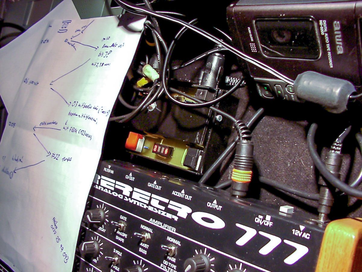
In the early 2000s a friend and me had an increasing number of live gigs. We were doing live Techno and Electronic Music by connecting our grooveboxes together and playing and jamming prepared patterns.
In this constellation we lacked a common source for our MIDI clock. One always had to be the master, the other one had to be a slave. It was not possible for the master to stop his sequencer to load another part of his set, because the slave would stop as well. It was also not possible for the slave to stop his sequencer, because some devices wouldn't allow to restart when the MIDI-Clock was running or you had to hit the sync-spot manually.
So we needed a device with two MIDI-Out-Ports. These two ports should stream MIDI-CLOCK-Messages (0xF8) continuously to both slaves. The processor counts the bars from 1 to 4, which is enough for dance music. A dial and a display should be used to setup and show the tempo in BPM.
And we need two buttons, one for each MIDI-Port. Button A requests a MIDI-Start-Message (0xFA) to be sent to MIDI-Port A. The main logic waits, until the internal timing is on the first bar, then sends the MIDI-Start-Message only to MIDI-Port A. The same happens with button B and MIDI-Port B.
The Hardware
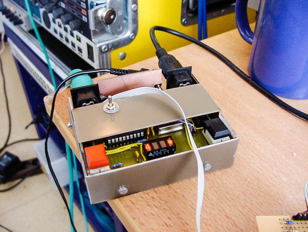
I used an Atmel AT90S2313, two Schurter-Buttons and a very cool Osram SLR2016 display. A voltage regulator 7805 created 5V. The AT90S2313 had only one UART, but I needed two for the two MIDI-Ports. So I used two NAND-Gates, connected the UART-output to both inputs A of the NAND-Gates and used two port pins from the Atmel to gate the UART-signal to the respective MIDI-Out. This allowed to filter out the MIDI-Start-Messsage. Together with my first attempt at controlling the display it was a nice entry drug into the world of Schematic Entry, PCB Layout and Embedded Programming.
I have etched the single-sided board in my university dorm. It was 2001 and cheap PCB manufacturers were still miles away.
For nostalgic reasons I have uploaded all files I have found to my Github-Account.
The Hardware-Repository (EAGLE)
The Firmware-Repository (Atmel Studio 4, but without any IDE-Files)


Version 2
The Version 2 should be a big upgrade with:
- 8 MIDI-Outs
- 1 MIDI-IN to sync to other MIDI-Gear
- 1 DIN-Sync Out, 1 DIN-Sync IN
- 8 dedicated switches, one for each port for each port
- 1 dedicated switch for a global Start-Stopp
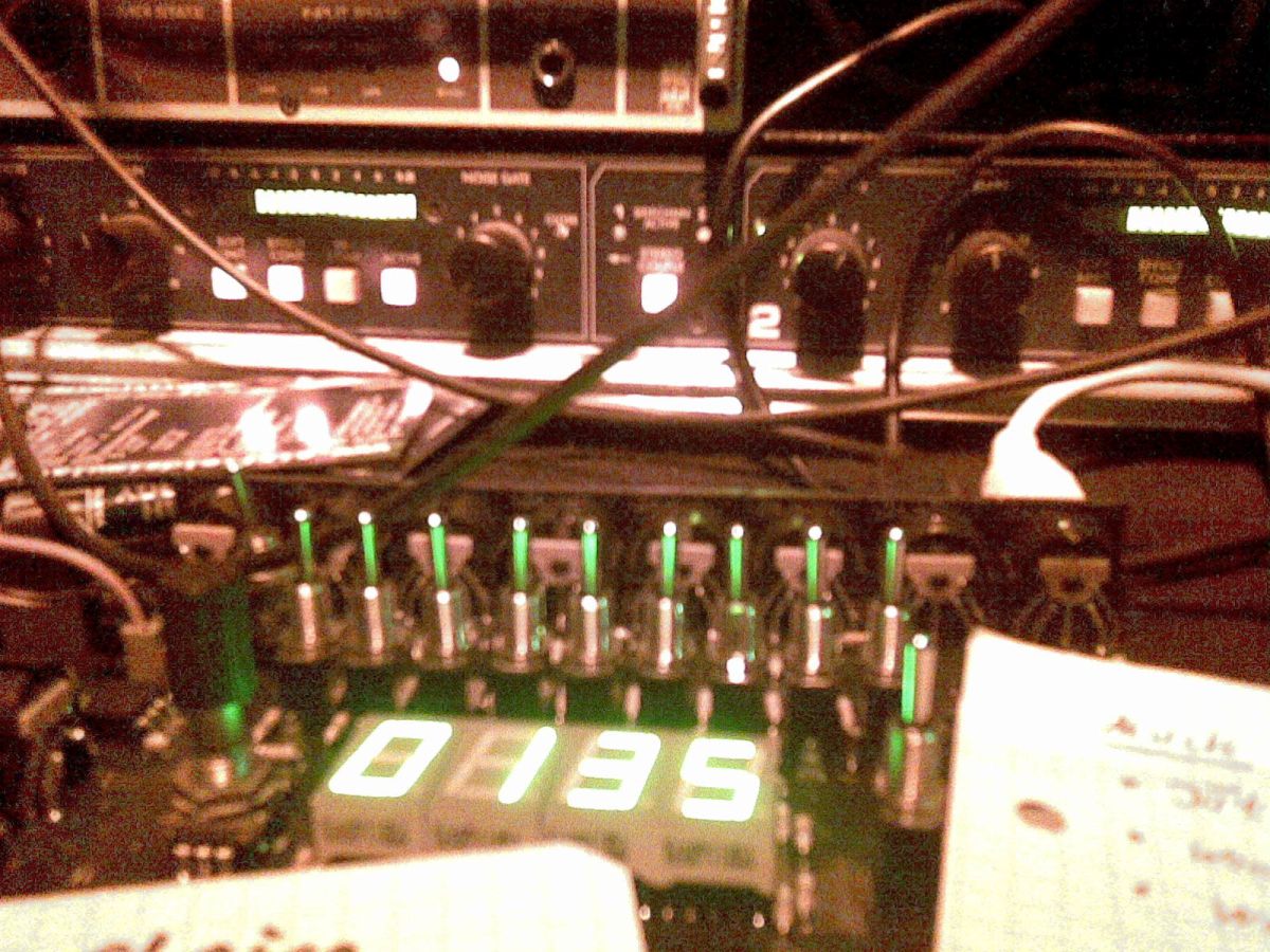
- The nice but expensive OSRAM-Display was switched against a stylish green 8-segment
- The Up-Down-Increase-Decrease-Buttons were replaced by a rotary encoder
I wanted to use Software-UARTs for the MIDI-Ports. Also the user should be able to shift them forward and backward in small units to correct offset-issues. This was too much for the small processor. Two MIDI-Ports were working, we used the device for some gigs in this state.
Programming-wise, what worked was the aquisition of the rotary encoder. The 10 levers and various LEDs were controlled using a LED-Button-Matrix.

